Make a call
Blog Details
02
Wed
Detailed introduction to the installation steps of Samson 3730-3 electric valve positioner
installation steps of Samson 3730-3
Detailed introduction to the installation steps of Samson 3730-3
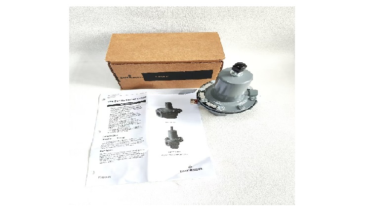
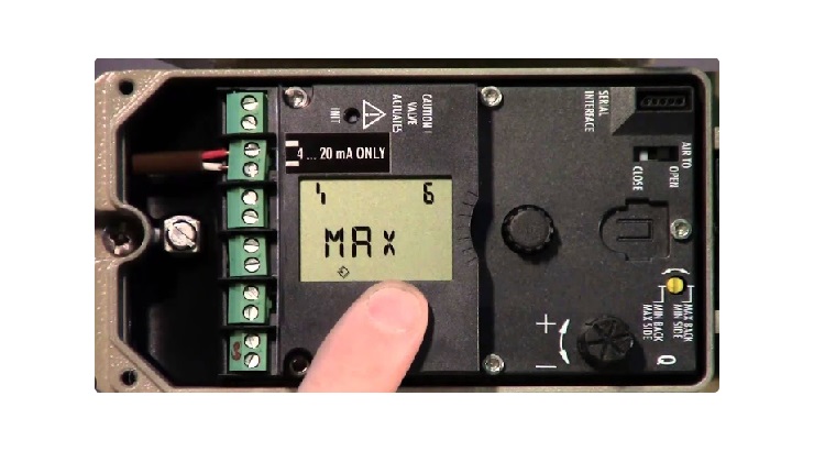
The installation of[ Samson 3730-3](https://www.cwlyautomation.com/product/3630.html " Samson 3730-3") electric valve positioner must be carried out in strict accordance with relevant specifications under the guidance of professionals to ensure its safe and stable operation. The following are detailed installation steps:
**Preparation before installation**
Confirm the installation environment: The positioner should be installed in a place with an ambient temperature of -20℃ to 80℃ and a relative humidity of 5% - 95%. Avoid installation in places with strong electromagnetic interference, severe vibration, and corrosive gases.
Check the integrity of accessories: After unpacking, carefully check whether the positioner and its accessories are complete, including the positioner body, installation accessories, instructions, certificates, etc. Check whether the appearance of the positioner is damaged or deformed.
Prepare installation tools: Prepare suitable tools such as screwdrivers, wrenches, levels, etc.
**Mechanical installation**
Linear actuator installation (according to IEC 60534-6, VDI/VDE 3847 standards)
Actuator cleaning: Clean the connection parts of the actuator, remove impurities such as oil, rust, etc., and ensure that the connection surface is flat and clean.
Mounting bracket: Use the matching mounting bracket and fix it to the actuator. During installation, make sure that the bracket is firmly installed. Use a level to check whether the bracket is level. If there is any deviation, adjust it.
Connecting the positioner: Connect the positioner to the actuator through the bracket and fix the positioner to the bracket with bolts. Note that the tightening torque of the bolts should be moderate to avoid over-tightening or over-loosening. Generally speaking, the tightening torque of M8 bolts is 12-15 N・m.
Connecting the feedback rod: Connect one end of the feedback rod to the feedback mechanism of the positioner and the other end to the valve stem of the actuator. Adjust the length of the feedback rod so that the positioner can accurately detect the stroke of the valve stem. After installation, the feedback rod should be flexible and free of jamming.
**Rotary actuator installation** (according to VDI/VDE 3845 standard)
Actuator interface treatment: Clean the interface of the rotary actuator to ensure that it is compatible with the positioner connection.
Installation of adapter: According to the interface size of the actuator, select a suitable adapter and install it on the actuator. The adapter should be installed firmly and accurately positioned.
Connection of positioner: Install the positioner on the adapter and fix it with bolts. During the installation process, the concentricity of the positioner and the actuator should be ensured, and the error should be controlled within ±0.1mm.
Adjustment of feedback mechanism: Adjust the feedback mechanism of the positioner so that it can accurately reflect the rotation angle of the actuator.
**Gas connection**
Gas source treatment: Ensure that the gas source is clean and dry, and the pressure is stable within the range required by the positioner (generally 1.4 - 7 bar). Install a filter and a pressure reducing valve at the gas source inlet to remove impurities and moisture in the gas source and adjust the gas source pressure.
Connection of gas source: Use a suitable gas pipe to connect the gas source to the gas source inlet of the positioner (marked as "Supply"). The connection of the gas pipe should be tight to prevent air leakage. You can use a pipe clamp or sealant to seal.
Connect the output air circuit: Connect the output air circuit of the positioner (marked "A" and "B") to the air chamber of the actuator. For single-acting actuators, only one output air circuit needs to be connected; for double-acting actuators, two output air circuits need to be connected. After the air circuit is connected, check whether the connection is firm and whether there is any leakage. You can use soapy water to apply to the connection part to check whether there are bubbles.
**Electrical connection**
Power-off operation: Before making electrical connections, make sure that the power supply is cut off to avoid the risk of electric shock.
Connect the control signal: Connect the 4-20mA control signal output by the control system to the signal input terminal of the positioner (usually marked as "+" and "-"). Pay attention to the polarity of the signal and ensure that the connection is correct.
Grounding connection: To ensure electrical safety, the grounding terminal of the positioner is reliably grounded. The grounding resistance should be less than 4Ω.
Check the electrical connection: After the electrical connection is completed, carefully check whether the connection is firm and whether there is any short circuit or open circuit.
**Post-installation inspection**
Mechanical inspection: Check whether the connection between the positioner and the actuator is firm, whether the feedback rod is flexible, and whether the components are loose or stuck.
Gas circuit inspection: Turn on the gas source and check whether there is any leakage at the gas circuit connection. Adjust the gas source pressure and observe whether the output pressure of the positioner is normal.
Electrical inspection: Turn on the power supply, check whether the display screen of the positioner is normal, input the control signal, observe whether the positioner can respond normally, and whether the valve can act according to the control signal.
Tags:
Our Latest Post

Our mission
Build strong relationships
with clients
Take responsibility for our customers, create value continuously,
and become a
trustworthy partner for industrial intelligence and connectivity.